Solar Tracker Notes
Notes about the solar tracker
Physical Setup
The following are stored in install_specific_settings.h so each tracker can customize them:
- Full west position: 2300 ticks
This gives about 30 ticks of padding to east and west before actuator reaches limit switches - Latitude/Longitude: tracker’s location
- Minimum actuator movement: 10 ticks
- Polynomial positioning coefficients: X3 X2 X1 X0 for multiplying times polynomial terms for the desired azimuth See the Polynomial Terms Calculation section.
User Interface
The UI consists of a display screen that turns on when the device is reset or when the user pushes the Status button, and 3 buttons to control the tracker.
![]()
The Display Screen
The screen times out after a short while to save power. If it’s off, just push the Status button to turn it on. It shows the following items (marked in the graphic):
- Time - This is the 24 hour UTC (not local) time. It should be correct or the tracker position will be incorrect as well.
- Position indicator - Prefixed with a “P” the position indicates the current position in ticks for the linear actuator. With the current actuator it should be between 0 (full east) and 910 (full west). Note that it does not update while the unit is moving, but will update when moves are complete.
- Tracking indicator - Prefixed with a “T:”, the tracking status will be either “Y” or “N”. When it shows “Y” the tracker will use the current time to position itself to point at the sun. When it shows “N”, automatic tracking is disabled. This is the only safe way to work on the physical structure because it won’t move automatically.
- Message - The message is context dependent on what you’re doing with it. When configuring, manually moving it around, disabling/enabling tracking, or if there’s an error condition- the message will show you something (hopefully) relevant.
The Buttons
The buttons marked in the graphic are the following:
- Status - If the screen is off, pushing the Status button wakes it up. If the tracker is in tracking mode and it’s moving, pushing this button will halt the tracker immediately and set tracking to disabled- useful if you forgot to disable it before doing something with the physical structure. It also has various functions during setup described later.
- East - When the screen is active, pushing the East button will move the tracker east and disable tracking. If you then hold the Status button and then release both buttons, the tracker will enter “auto move” mode and move to position 0 (the east limit).
- West - When the screen is active, pushing the West button will move the tracker west and disable tracking. If you then hold the Status button and then release both buttons, the tracker will enter “auto move” mode and move to position 2300 (the west limit).
Setup After Reset
If the controller loses power (or you push the reset button on the Arduino, or plug in a laptop to reprogram or look at the Arduino IDE’s Serial Monitor), it will not remember what position it was at. If the screen is still on after reset, you can configure the position. If the screen has already shut off, just hit the Status button to wake it up.
In this case, the display message should read “Setup Required” and the Position indicator will say “P UNK” for “unknown”. If the tracker is not at the east limit, use the East/West buttons to move it until it hits the east limit switch. Move it back west for a second or two (ideally about 30 ticks which you can also get by using the status button to zero, then moving then re-zeroing) so we don’t hit the limit switches every day (hopefully increases their lifespan).
Once positioned at the east limit (minus some padding), push the Status button and release it. The display message should say “Press to zero”. Press and release the Status button. The display message should say “Position zeroed” followed shortly by “Danger! Tracking!”, the Position indicator should switch from “UNK” to “000”, and the Tracking indicator should switch from “N” to “Y”. While it doesn’t move quickly, this is your hint to make sure you haven’t left any tools/clamps/children/etc. in a dangerous position. If it’s during daylight tracking hours, the tracker will move to the position it should be at for the current azimuth angle of the sun. If it’s outside tracking range, it will not move.
Since all this is a pain, try to only cut power (or cause a reset) when the tracker is sitting at the east limit. This makes it very easy- you just hit the Status button again when the display is active, it will ask you to press again to zero, and you’re done. It will be tracking at that point with no fuss.
Physical Structure Maintenance
Since sometimes you may need to work on the physical structure (maybe changing out a broken panel, putting wires in conduit, etc), it is helpful to have the tracker stop moving or manually move it to a different orientation. While you can just unplug the controller and reset it once you’re done, it’s probably easier to put the controller into “tracking disabled” mode. In this mode it will not move until you re-enable tracking mode.
To do this, hit the Status button to wake up the screen. Hit the Status button again and the display message should say “Tracking disabled” and the Tracking indicator should say “T:N”. The Tracking indicator is there so when the message changes after you push other buttons, you’ll still know it’s not tracking and it’s safe to work on the structure. It will never go from “N” back to “Y” without you telling it to.
You can use the East/West buttons to manually move it to a different orientation if needed. WARNING: you can exceed the movement limits by holding the East/West buttons!!! Use them with care. While moving the Position indicator does not update, but it will update after you release the movement buttons.
The “auto move” feature is handy to move it full east or full west without sitting there holding the button for several minutes (see the Buttons section for auto move instructions). Auto move is also nice because you don’t have to worry about exceeding the movement limits (unless the tracker has been improperly zeroed at somewhere other than the east limit of course).
To re-enable tracking, make sure the display is active and a position number is displayed in the Position indicator (if it says “P UNK” then the controller lost power during your maintenance and needs to be zeroed at the east limit, see Setup After Reset) then hit the Status button again. The display message should say “Press to enable” (if it says “Press to zero” instead- stop! Follow the Setup After Reset directions instead.). Pressing the button again will re-enable tracking. It will say “Tracking enabled” followed shortly by “Danger! Tracking!” as the tracker is likely off of its correct position for the time of day (assuming it was disabled for more than a couple minutes).
Error Situations
There are a few planned error situations. The following errors will show up on the screen when you press the Status button and won’t let you do anything else until they’re resolved.
RTC Lost Power
This is a pain two reasons:
- It means the backup battery (one of those flat watch batteries) in the ChronoDot (the round timekeeping device attached to the Arduino) is dead. Look in the electronics closet- there’s another ChronoDot there in one of those boxes that has a bunch of little components (wires/resistors/buttons/etc.). In the segment with the ChronoDot is another battery.
- There is currently no way to set the clock using the buttons. This is to discourage people setting the clock without replacing the battery. The clock would only run with a dead backup battery until the next time the controller loses power so this would be bad.
To set the clock (after replacing the battery), load the Solar_Tracker_Positional.ino file in the Arduino IDE. Locate the following code in the
void setup()function:/* #define TZ_OFFSET -8 // Pacific Standard Time (Pacific Daylight Time is -7) DateTime localDateTime = DateTime(F(__DATE__), F(__TIME__)); time_t localSeconds = localDateTime.unixtime(); // convert local seconds to UTC seconds and date time time_t utcSeconds = localSeconds - TZ_OFFSET * SECS_PER_HOUR; DateTime utcDateTime = DateTime(utcSeconds); // set the RTC with utcDateTime rtc.adjust(utcDateTime); */Uncomment this section. Modify the TZ_OFFSET based on current time zone (for us, either -8 for PST or -7 for PDT). Connect your laptop with the USB cable to the controller, set the board/port in the Arduino IDE to “MEGA 2560” and whatever the correct USB port is (something like /dev/cu.usbserialxxx on my mac), then upload the program. The display message on the LCD screen should show “Needs setup”. Do not unplug the computer or the next time the power fails, the clock will be set incorrectly and the tracker will likely be WAY off. Comment that code out again, and upload the program again- this way when the battery dies years later you’ll get this message again and know what’s wrong with it. Now disconnect the laptop and proceed to the Setup After Reset section.
Motor Sense Err
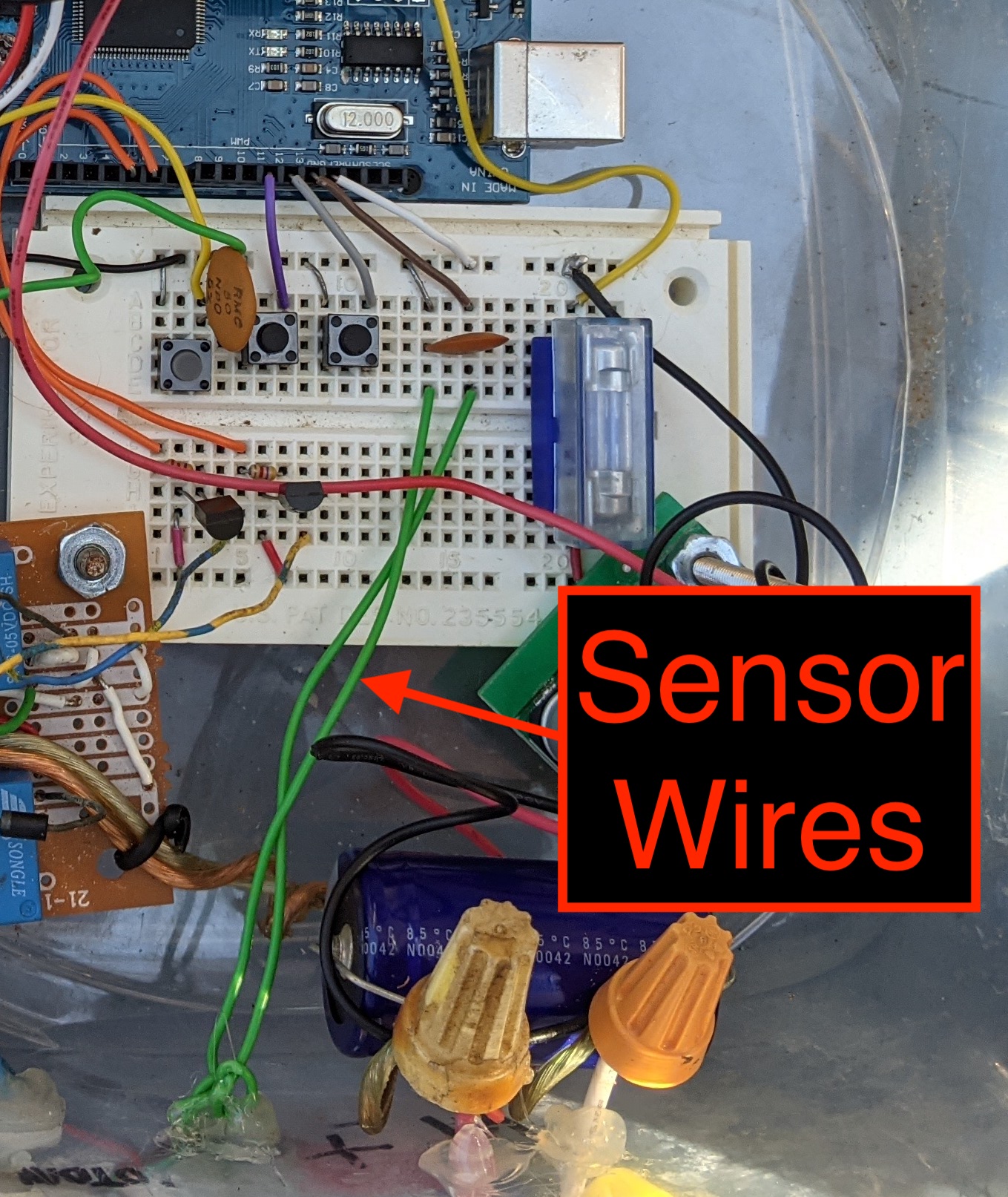
A motor sense error means when the tracker was moving, it didn’t see any ticks from the position sensor for 3/4 of a second. This is a clear error condition telling the controller that a sensor wire is broken/pulled/etc. and it can no longer determine what the actuator position is. This is probably relatively easy to fix as it’s likely a broken/disconnected wire, but it can also be a physical obstruction or a problem with the linear actuator.
To resolve this if it doesn’t appear to be a physical problem, reset the controller and then use the east/west buttons to test if the motor moves. If it’s not moving, check if the buttons are sending power to the motor. If it is moving fine by those buttons, disconnect power to the controller. Check the two green wires coming out of the controller- these are the sensor wires.
 Try the following steps in order to determine the problem:
- Make sure they’re still plugged in to the breadboard. Refer to the photo above. Make sure the capacitor is still securely plugged in and didn’t get bumped too much by someone pushing buttons.
- Make sure the brown wire going into the Arduino from above the capacitor hasn’t gotten unplugged. If it has, it’s pin 13 on the Arduino (between the gray and white wires in the picture). The bare ground wire seems unlikely to have been removed on accident.
- Unscrew the 4 screws on the actuator’s access panel. Using a tester, test for continuity on each green wire from where it connects on the breadboard to the wires coming from the sensor in the actuator.
- If none of that solved it, here’s some info to help you figure it out. The sensor in the actuator is a reed switch. As the motor moves, the wires from the sensor go from a closed to open circuit (just like a button). About 3/4 of the time the circuit is closed and you should have continuity from one green wire on the breadboard to the other one. The other 1/4 of the time, the circuit is open and there should not be continuity between the green wires- but there should be continuity from each green wire to its corresponding wire on the reed switch. If this all seems correct, the remaining possibility is damage to the Arduino. To determine if that’s the case, you’ll need to take this thing to your desk and write a test program to show when the green wires are connected and when they’re not. If this program fails, then that port is dead. Try another port. Or another Arduino.
Polynomial Terms Calculation
A third degree polynomial can quite accurately reproduce the motion of a plane rotated about an axis by a linear actuator (i.e. the azimuth that the tracker will face given a certain number of ticks of movement by the linear actuator). This is calculated by manually moving the tracker through small increments of its range, and copying down the position reading from the controller and the azimuth that the tracker is facing at that position. This ends up with a table of azimuth to position. Feed this into a polynomial regression calculator like this one. It should look something like this:
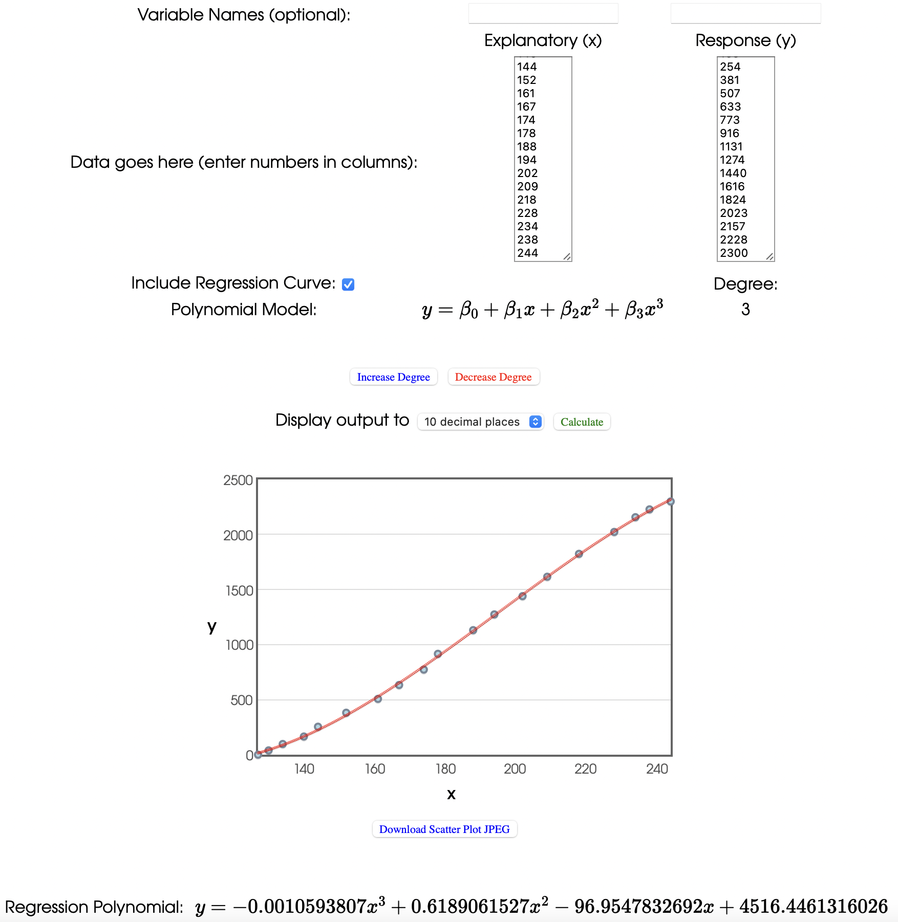
The Explanatory (x) variable is the azimuth you want to achieve (because the controller knows what azimuth the sun is at), and the Response (y) is the linear actuator’s position that points the tracker at that azimuth. In my case, the result isn’t that far off from a straight line, but if you try a simple linear regression then the resulting accuracy can be off by over 10 degrees at times. So it seems worth the small amount of time required to collect those points (it was windy when I collected this so you can see some of them fall a bit off the line) to get the resulting accuracy.
To use this, just take the X3 to X0 coefficients and plug them into the install_specific_settings.h file, recompile, and upload to the controller. Re-zero the controller and watch it track to within a few degrees of the sun’s current position with no visual reference to the sun.
Source Code
Source is at https://github.com/jpangburn/Solar_Tracker_Positional