Von Weise Linear Actuator Fix for model v76-5
This document contains the process for fixing the nylon nut in a Von Weise linear actuator model v76-5. The part number for the nut is v76-202 but I was unable to get a response from Von Weise for getting a replacement.
Short Version
Do the following:
- Download this STL file for the nylon nut
- Get it printed in MJF nylon with millimeters as the units at CraftCloud, I got mine printed/shipped for $18 and change.
- Replace the old nylon nut with this one
- Enjoy the rest of your life
Detailed Version
Step 1: Print a New Nut
It takes a while to get the nylon nut 3d printed/shipped, so this is the first thing you should do. I have a 3d printer but only have PLA plastic for it which isn’t great for this job, and it’s an FDM printer so threads don’t come out that great. Used my printer to prototype it, but then used CraftCloud to get it printed in impact resistant nylon using an MJF print process which does threads a lot better. Getting the nut out of the tube is a pain in the butt, so you don’t want to keep doing this- get it printed by professionals so you only have to do this once.
You have two options for printing the nut. The first time I printed the nut in nylon it fit but was way too tight (I used the exact ACME 3/4” thread settings which doesn’t leave any space at all because I don’t know much about printing threads). So I backed off the thread faces by 0.005” and the thread root/crest by 0.003”. It works great and fits on easily but I wonder if it should be more snug than this so it will last longer. This file is here. If you choose this file you can be certain it will work.
I made another version with tighter tolerances where the faces are backed off by 0.003” and the root/crest by 0.002”, but I have not tried it. If someone tries it, please let me know how it works out. It’s available here. If it still moves easily enough to be usable, then it would last longer but it may be too tight- I don’t know.
There are lots of websites for 3d printing, but I like CraftCloud because they shop your part around to a bunch of suppliers to see what the various materials/costs are. Kind of like an Orbitz for 3d printing. I’ve used them a few times and things have always turned out well. Here’s a link to CraftCloud’s Upload Page. It will default to millimeters as the unit type, and that’s correct because although the part was designed in imperial units the export file is created in millimeters.
Get it printed in MJF nylon (MJF seems to make better threads than the FDM process), I got mine printed/shipped for $18 and change. You can get it cheaper using FDM but I don’t recommend it. Here’s a couple screenshots in case it helps:
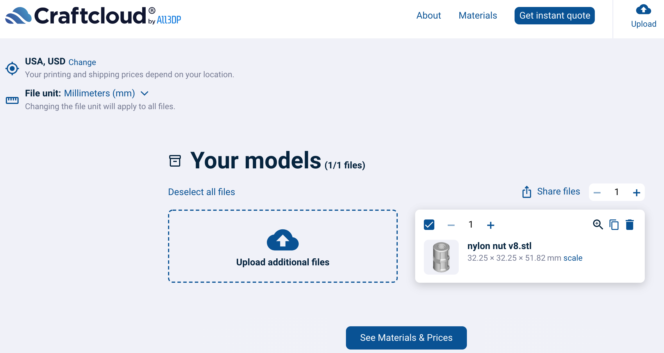
That’s what it should look like after you upload the STL file, make sure your dimensions are the same. Then click “See Materials & Prices”. Use the filter on the left to select “nylon” as the material you want, then find one using MJF technology (I used MFJ Nylon PA12):
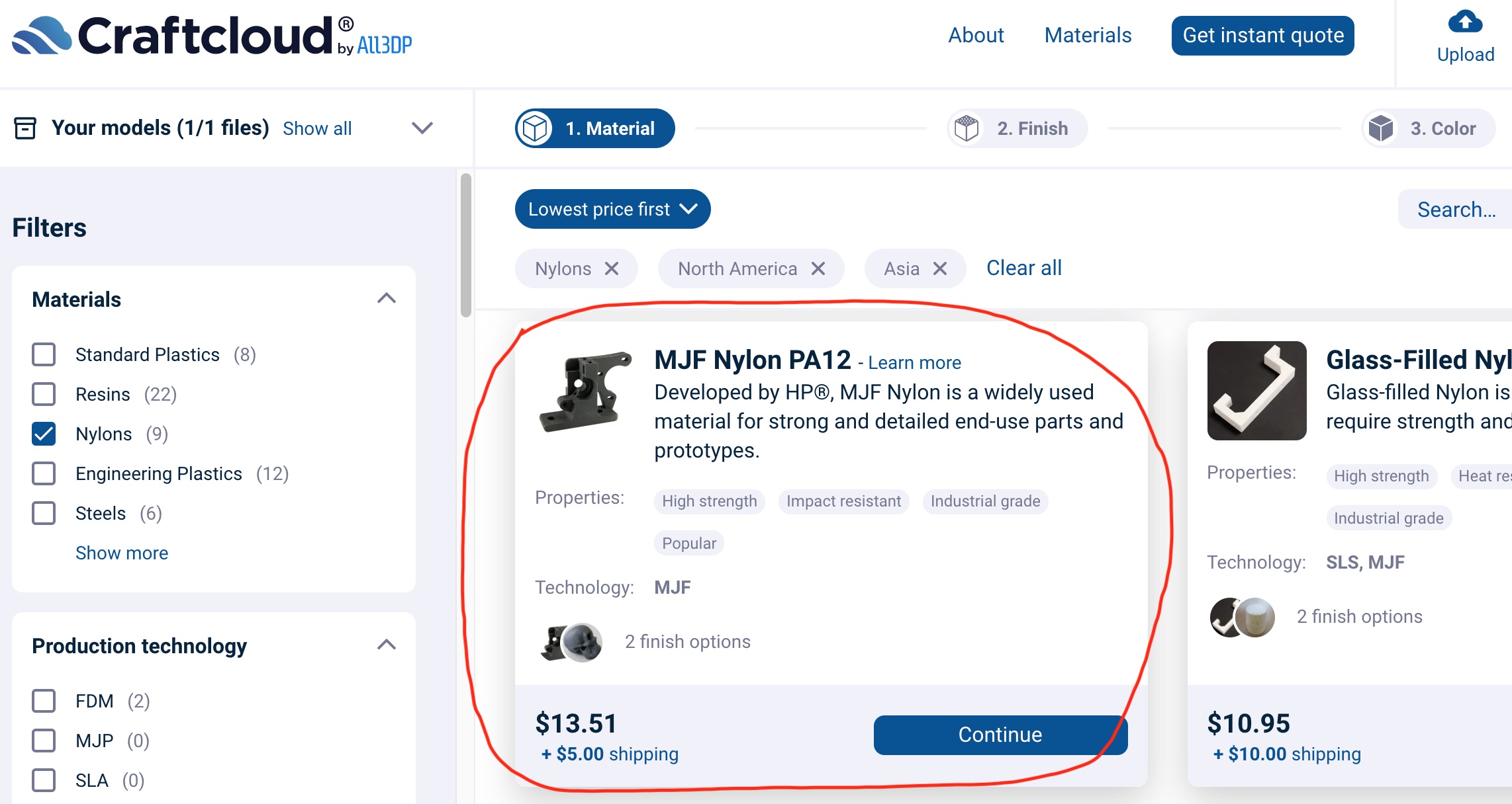
After you click “Continue” it’ll ask if you want it Raw or Polished. I chose Raw- who cares if it’s polished, no one but you will see it. After that you can choose colors, I chose the color that didn’t cost extra- gray. Billing/shipping you can figure out on your own.
Step 2 Remove the old nut
While you’re waiting for your new nut to print/ship, it’s time to get the old one out. Since you’re reading this, your actuator is likely already in two pieces because the nylon nut is wrecked- unthread the inner tube if not. For consistency, I’ll refer to the smaller tube that moves back and forth as the “inner tube” and the larger tube with the threaded rod inside of it as the “outer tube”. The nut is fixed inside the inner tube and needs to be removed. There are metal tabs that are cut into the inner tube that are pressed in place around the nut and these keep it from moving.
I’ve seen a post from someone who cut their tabs to remove the nut, put a brass nut in its place, and welded the tabs back in. While that’s probably fine for a brass nut, it’s maybe not a great plan for a nylon nut due to the heat. But if you prefer that method and think you can do it without melting the nylon, it’s an option.
For me, I thought it would be easier to just cut the nut out with a reciprocating saw (like a jigsaw) and bend the tabs out. Here’s how that looks:
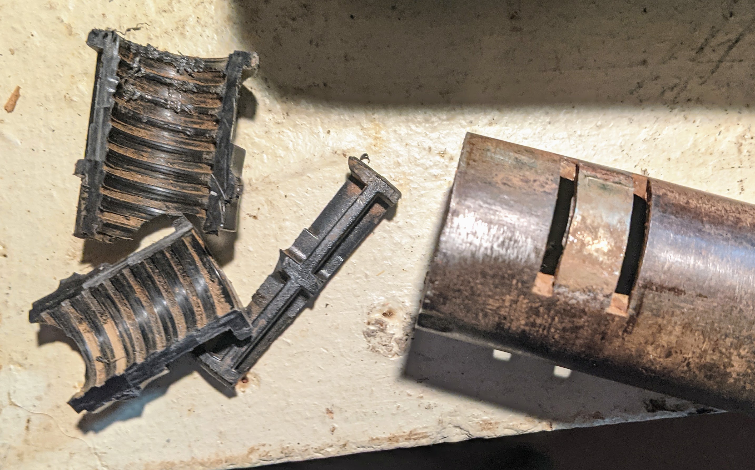
The nut is in pieces from the saw.
Step 3: Spread the Tabs Back Out
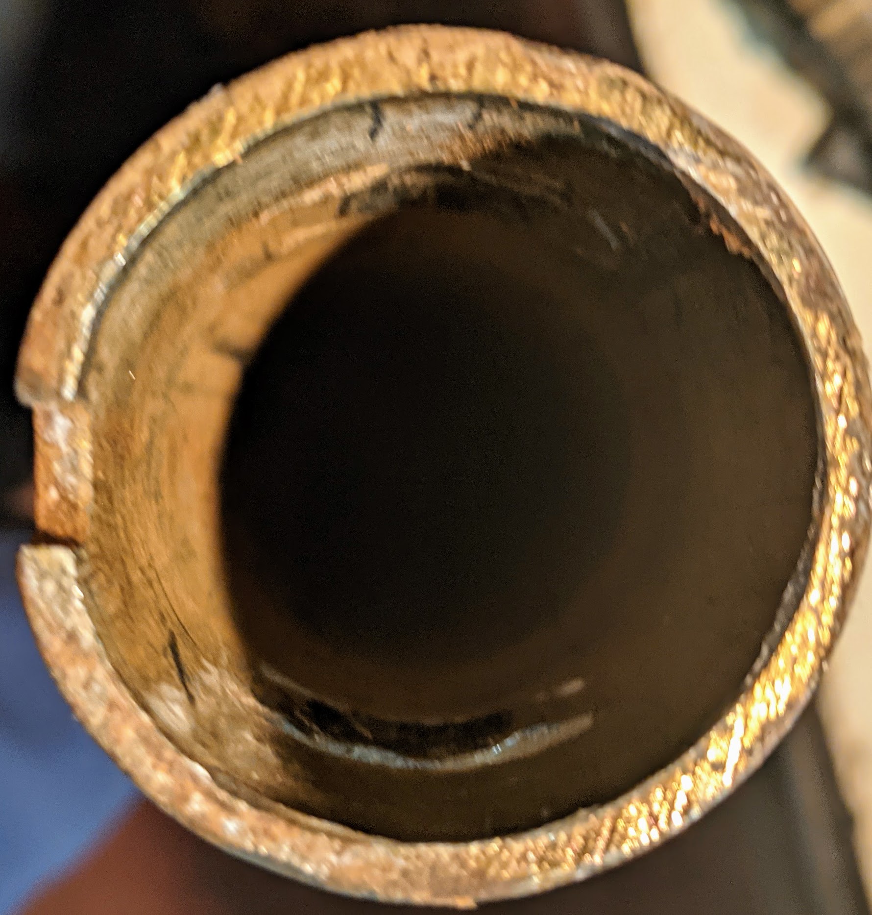
In the inner tube, the tabs are pressed in, but you need them spread back out so you can put the new nut in when it arrives. How you do this depends a lot on what you’ve got laying around your shop. I just found sequentially larger pipe wrenches that have nice round handles and pounded them through the tube to spread the tabs a little wider each time. Whatever you do, just take care not to wreck the tabs and get them to be spread out enough so they match the diameter of the inner tube- it needs to be round so the new nut will fit in. The nut fits in the inner tube tightly, so they need to be pretty rounded out.
Here’s how mine ended up looking:
Step 4: Lube the Threaded Rod In the Outer Tube
Inside the outer tube is the threaded rod. The nut rides back and forth on this to make your linear actuator… linear actuate? In any case, part of the reason your nut wore out is from the threaded rod sanding down the inside of your nut. So to slow this process down on your new nut, you should lube that threaded rod.
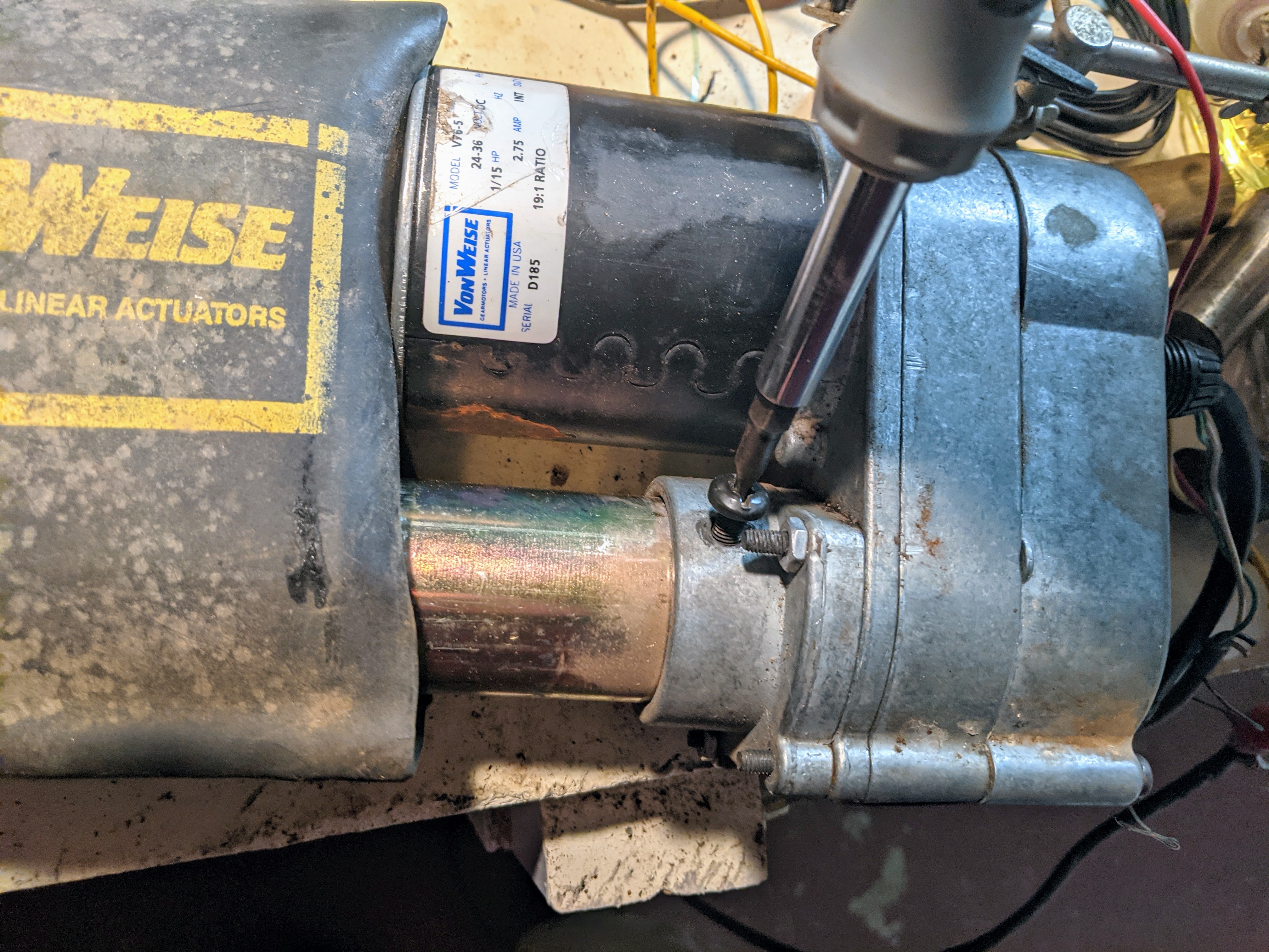
To do this, just unscrew the 3 screws that hold in the outer tube to the motor. They are these screws:
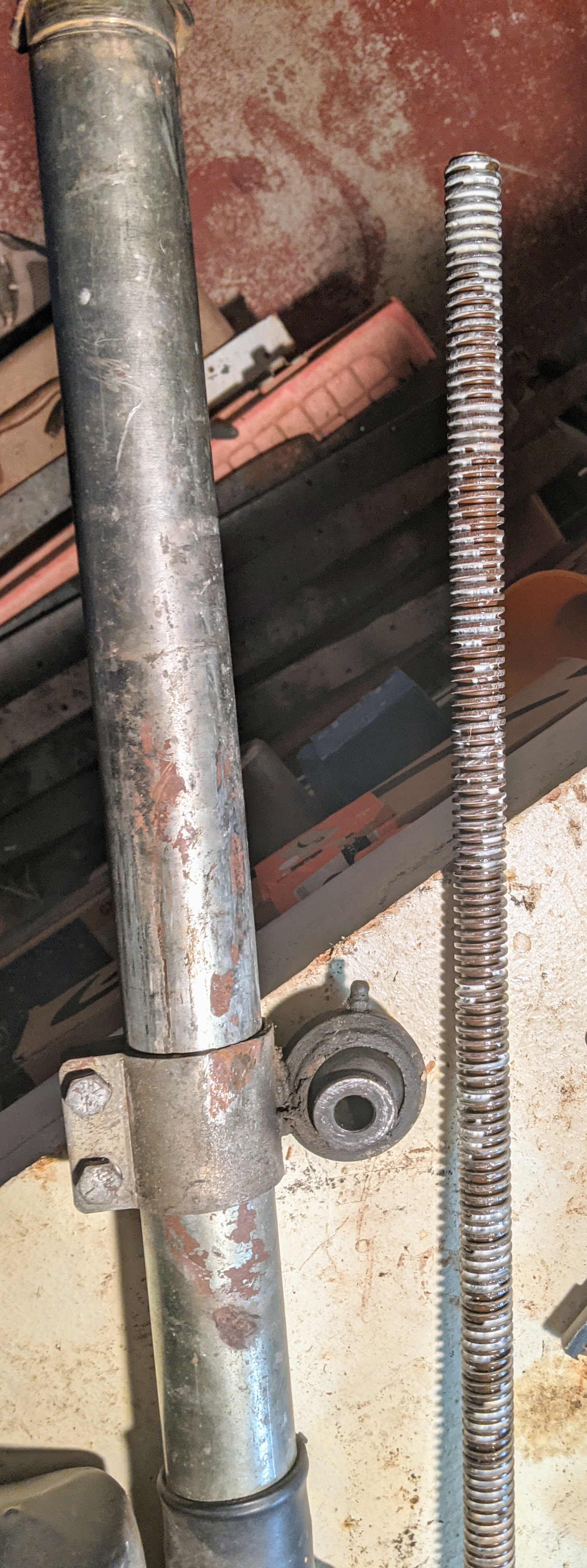
Remove the outer tube, and apply whatever grease you have that you think will work best. I used white lithium spray on grease which works well. Here’s a photo of the outer tube next to the greased threaded rod:
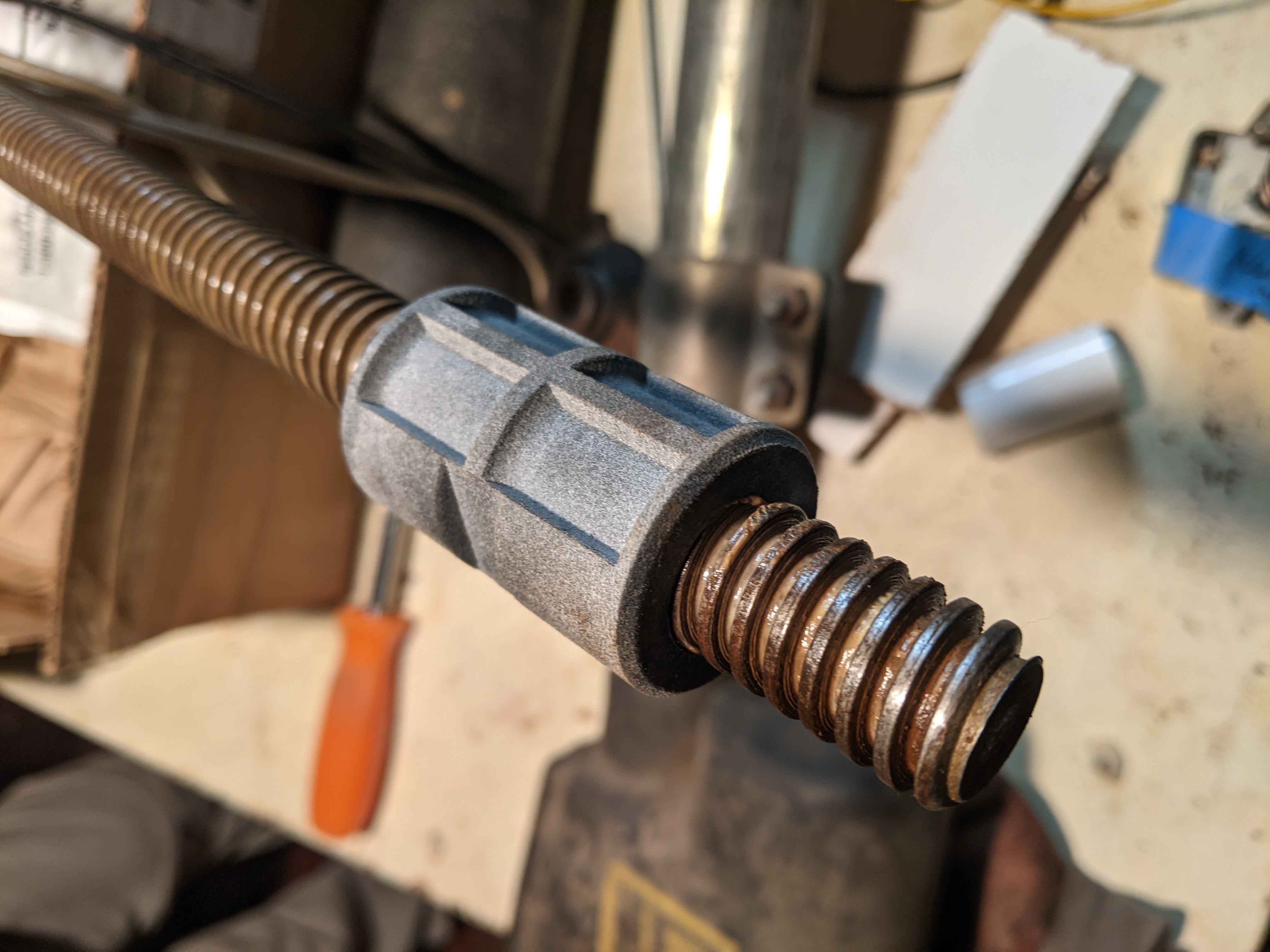
Step 5: Check Nylon Nut on Threaded Rod
Yay, your new nylon nut showed up in the mail! Screw it onto the threaded rod to make sure it fits well (it’s possible your print did not come out well, especially if you ignored the MJF advice).
Assuming it turns smoothly, remove the nut from the threaded rod. Reconnect the outer tube onto the motor with the three screws.
Step 6: Install Nylon Nut in Inner Tube
Look at the new nylon nut, see the two flat spots on the side? Those are supposed to be held tightly by the tabs you spread out in step 3. Gently tap the nut into the inner tube using a rubber mallet if it fits snugly like mine did, being very careful to align the flat spots on the nut with the tabs on the inner tube. There is no extra room in the flat spots- they must be aligned precisely with the tabs on the inner tube (this is designed this way so the nut doesn’t try to slide back and forth in the inner tube). When you’re certain the nut is aligned precisely in the inner tube, carefully crush the tabs onto the nut to hold it in place. I used a vice with a couple screwdrivers like this:
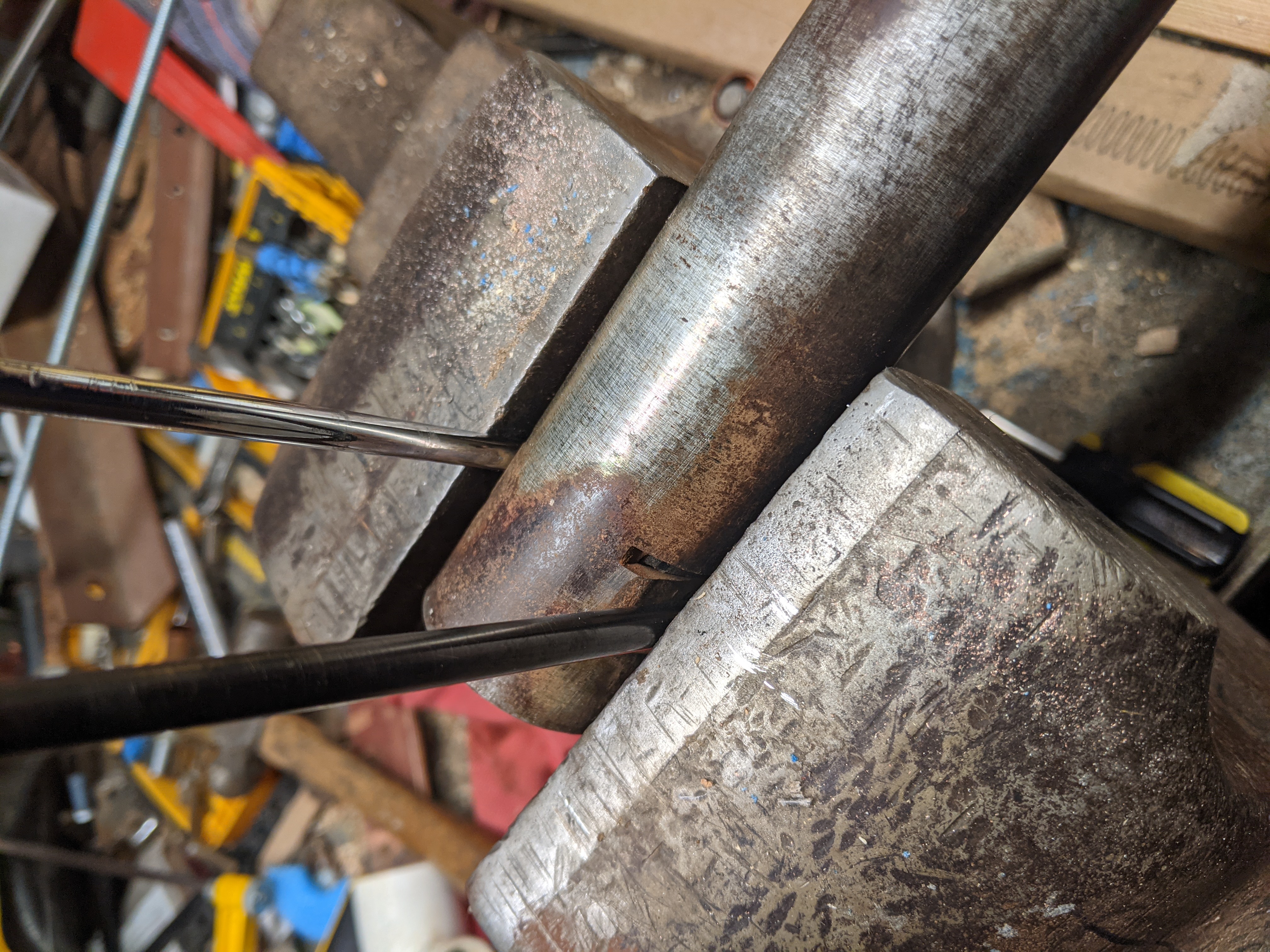
This let me crush the tabs exactly as much as needed. Don’t go too far or you’ll crush the nylon nut, but go far enough so it’s held tightly. Worst case though, you crush the nut, order another one, and try again.
Step 7: Reinstall Inner Tube Inside Outer Tube
Run the motor until it hits the fully extended limit. On my motor this means connecting positive voltage to the black wire and ground to the white wire. Looking at the rod from outside the outer tube it should be turning clockwise. This is so when you attach the inner tube it doesn’t stop halfway in.
To install the inner tube in the outer tube, it’s easiest if you stand the outer tube up vertically so the threaded rod inside can be tipped a little so it sits in the center of the outer tube. Then align the inner tube above it and screw it into the outer tube. Turn it in until the nut is about halfway onto the threaded rod- basically you don’t want to go too far because when you fully retract it you REALLY don’t want it to bind at the physical limit before it hits the limit switch!
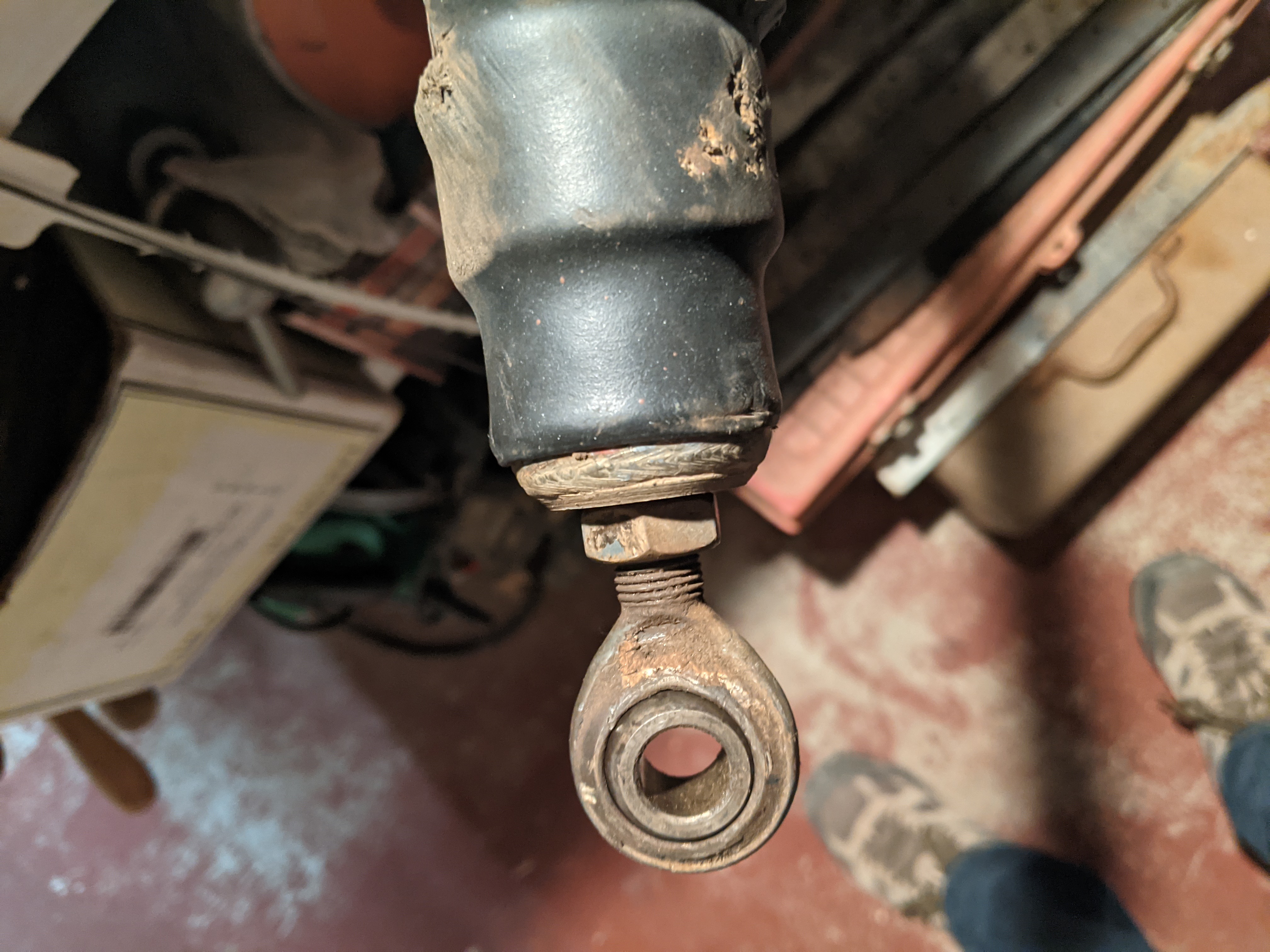
Hold the inner tube so it doesn’t turn and run the motor the other direction until it hits the fully retracted limit. For my motor, this means positive voltage is connected to the white wire, and ground to the black wire. When I ran it all the way in it looked like this:
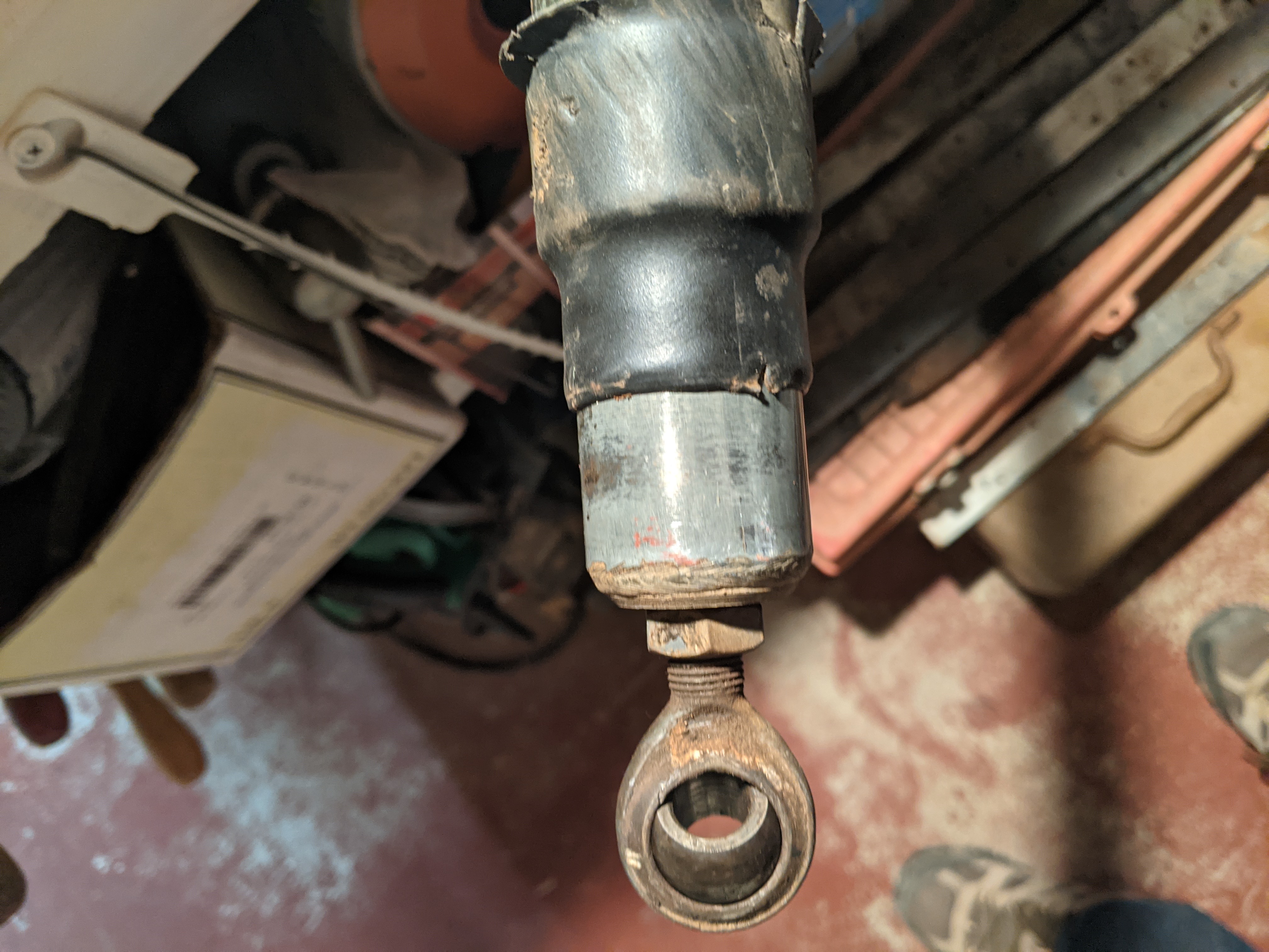
Now turn it in until the shoulder of the inner tube is just about to the rubber sleeve that goes around the two tubes, like this:
You’re Done!
Hope you found this helpful! Enjoy linearly actuating stuff :-) A solar tracker in my case.
If you tried the tighter fitting STL file and it worked well, please let me know so I can update this page with that info for others. Or leave a comment if you like!